

This article will provide the step by step instructions to setup the Cisco UCS environment for first time. Cisco UCS is highly customizable and the configuration will be differ for each environment. The core part of Cisco UCS deployment is cabling. Unlike the traditional chassis , Cisco UCS have additional components like I/O modules (FEX) and Fabric interconnects (FI / UCS Manager). Fabric interconnect has its own management ports to manage it. There will be a dedicated ports to provide the connectivity between FI’s. So that both the FI’s configuration will be sync with each other.
1. Setup the Fabric Interconnect (UCS Manager) . You need to interconnect the FI’s to make the FI cluster.
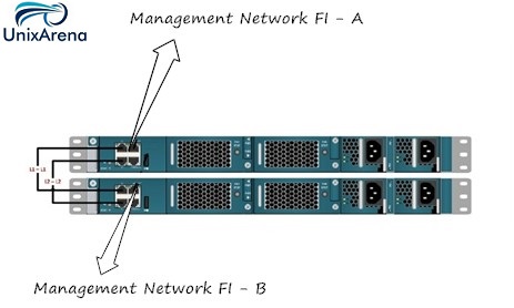
The Fabric interconnect’s MGMT port needs to be connected to the management network. Connect the L1 port of Fabric Interconnect “A” to the L1 port of fabric interconnect “B”. Do likewise for the L2 ports. L1 & L2 ports are used for Fabric interconnect heart-beating and this connectivity ensures that both the FI’s maintaining the identical data.
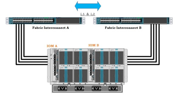
2. Laid the cabling between the chassis and Fabric interconnect. So that chassis can be discovered in the UCS manager. L1 & L2 ports provides the connectivity between two FI’s.
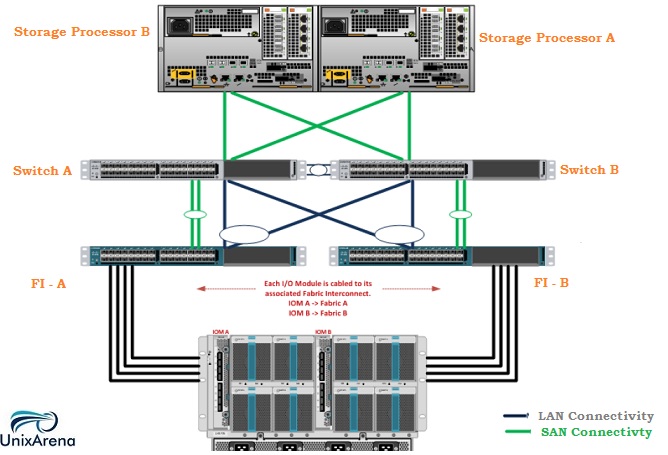
3. Connect the FI’s to the Nexus switch. This Nexus switch has capability to diverging the LAN & SAN traffic to the peer devices.
At this point , you have physically setup the UCS environment.
4. Configuring the Fabric Interconnects.
Connect to the console port of Fabric Interconnect (FI) “A”, which will be the primary member of the cluster. Power on FI-A and leave the secondary FI off for now. Verify that the console port parameters on the attached computer are as follows “9600 baud”, “8 data bits”, “No parity”, “1 stop bit”. Once you have connected to the FI – A management console, you will get the interactive session like below.
Enter the configuration method. (console/gui) ? console
Enter the setup mode; setup newly or restore from backup. (setup/restore) ?
setup You have chosen to setup a new Fabric interconnect. Continue? (y/n): y
Enter the password for “admin”: password
Confirm the password for “admin”: password
Is this Fabric interconnect part of a cluster(select ‘no’ for standalone)? (yes/no) [n]: yes
Enter the switch fabric (A/B) []: A
Enter the system name: Fabric-DC1-A
Physical Switch Mgmt0 IPv4 address : X.X.X.X
Physical Switch Mgmt0 IPv4 netmask : X.X.X.X
IPv4 address of the default gateway : X.X.X.X
Cluster IPv4 address : X.X.X.X (NOTE: This IP address will be used for Management)
Configure the DNS Server IPv4 address? (yes/no) [n]: y
DNS IPv4 address : X.X.X.X
Configure the default domain name? (yes/no) [n]: y
Default domain name: domain.com Apply and save the configuration (select ‘no’ if you want to re-enter)? (yes/no): yes
Now connect to the console port of the secondary FI and power it on. Once again, you need to follow like below.
Enter the configuration method. (console/gui) ? console

Installer has detected the presence of a peer Fabric interconnect. This Fabric interconnect will be added to the cluster. Continue (y/n) ? y

Enter the admin password of the peer Fabric interconnect: password

Physical Switch Mgmt0 IPv4 address : X.X.X.X

Apply and save the configuration (select ‘no’ if you want to re-enter)? (yes/no): yes
Both Fabric Interconnects should now be configured with basic IP and Cluster IP information.
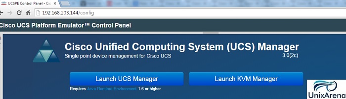
5. Launch the UCS manager using the cluster IP. Click “Launch UCS Manager” .
6. Once the UCS manager is launched , you need to configure certern polices to scan the chassis. Hope this article is informative to you.
In the Next article ,we will see that how we can scan the chassis using the UCS Manager.