

Once you have done the Cabling and Fabric Interconnect’s cluster configuration, the next step would be to configuring the polices and configure ports to perform the chassis discovery. In this article,we will see that how we can configure the equipment policies and discovery the chassis. Once the chassis is discovered , you can see the chassis components like server modules , IO adapters in the UCS manager’s Equipments tab.
Configuring the Equipment policy:
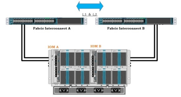
1. Here the assumption is that we have only two connections from each IOM to FI’s.
2. Login to UCS manager .
3. Select Equipment – > Policies – > Global policies .
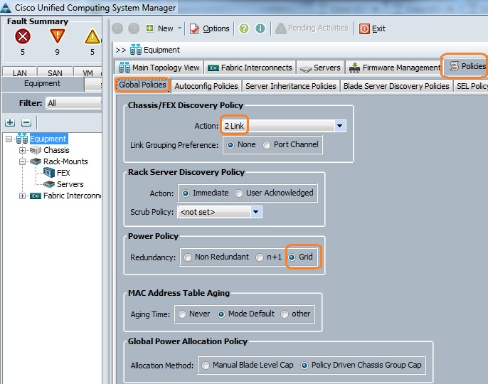
In Chassis/FEX discover policy tab,
“Action:” dropdown should be set to the amount of links that are connected between an individual IOM and Fabric Interconnect pair. For instance, in the drawing displayed earlier each IOM had two connections to its associated Fabric Interconnect. Thus, a “2 link” policy should be created. This policy is essentially just specifying how many connections need to be present for a chassis to be discovered. There is no harm if you use default link value (1) , but setting the actual “No of Links” will help you identify the bad links between FEX/IOM to FI.
In Power Policy tab,
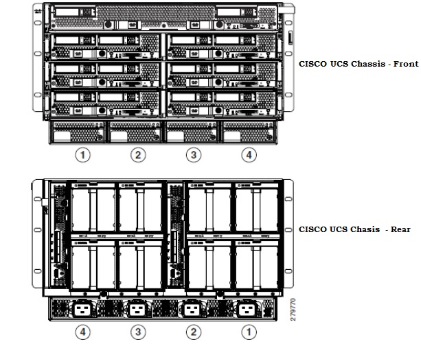
For environments with redundant power sources/PDUs, “Grid” should be specified for a power policy. If one source fails (which causes a loss of power to one or two power supplies), the surviving power supplies on the other power circuit continue to provide power to the chassis. Both grids in a power redundant system should have the same number of power supplies. Slots 1 and 2 are assigned to grid 1 and slots 3 and 4 are assigned to grid 2.
Configuring Ports:
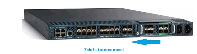
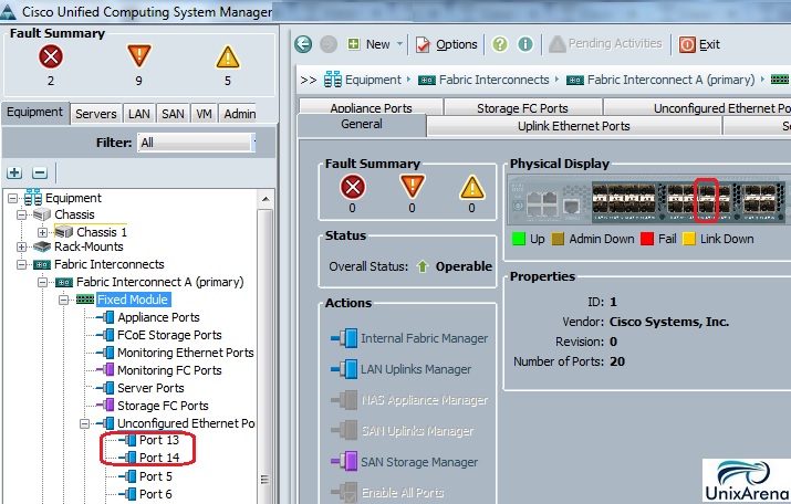
1. Navigate to the “Equipment” tab – > Fabric Interconnects – > Fabric Interconnect A/B . Then expand any Fixed or Expansion modules as necessary. Configure the appropriate un-configured ports as “Server” . The best practice is to configure the ports from middle or last of the FI. The ports which you are configuring be will act as FCoE and remaining ports also will be configured as FCoE .
Note: You have to do the cabling accordingly from IOM to FI. For an example ,if you have connected to the port number 11 and 12 ports from FI-A to IOM – A & 11 and 12 ports from FI-B to IOM – B , you need to configure only those ports.
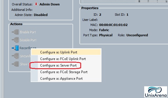
2. Right click the port and configure as “server port” for each port that you have connected with IOM (Chassis.)
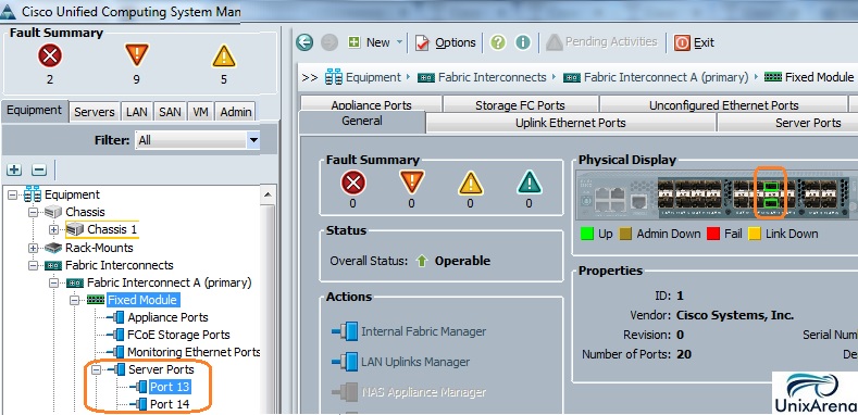
3. After configuring the server ports on Fabric interconnect A , you can see the link status like below. (Green link on the FI).
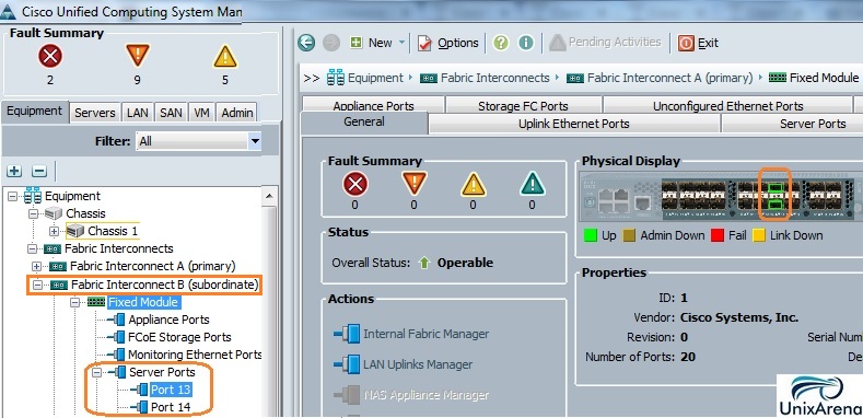
4. Same way you need to configure the ports on fabric interconnect -B .
Once you have configured the ports , chassis will be discovered and it will be listed under the equipment tab. In the above screenshot, you can see that chassis 1 has been discovered.
Acknowledging a Chassis:
Refer: Cisco Product Guide for more information.
Hope this article is informative to you.